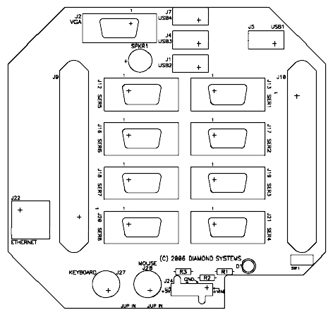
Figure 1: Panel Board, User Side
This manual provides the information needed to use the Pandora Enclosure with Diamond Systems PC/104 CPU cards, including Athena, Elektra and Prometheus.
The manual includes,
Pandora provides an easy to assemble, lightweight, rugged and flexible enclosure for PC/104 systems. There are two versions of the Pandora enclosure.
This standardized interconnect scheme speeds up the assembly process and improves reliability and ruggedness. A panel I/O board plugs directly onto the Diamond Systems CPU card and converts all CPU I/O signals to industry-standard connectors. The panel board then mounts directly to the matching front panel of the enclosure. The entire PC/104 stack is held firmly in place with direct connections to both the top and bottom of the enclosure for extra rigidity. The rear panel provides convenient corner holes for quick mounting of the complete system.
The new Pandora Panel I/O Board is compatible with Diamond Systems Elektra, Athena, and Prometheus CPU boards. All three CPUs contain the same set of I/O connectors, with the same features in the same locations. The Pandora Panel Board has connectors for basic computer functions, including keyboard, mouse, VGA, Ethernet and USB. With the Pandora enclosure, you can build a rugged, cable-free PC-based controller using the CPU of your choice.
The Pandora Panel I/O Board design also accommodates up to two add-on PC/104 modules without requiring costly and time-consuming enclosure redesign. A supplementary 50-pin connector can be used with any PC/104 board with a 50-pin I/O connector to provide additional analog or digital I/O to the outside world. Two additional 20-pin connectors can be used with any model of Diamond Systems Emerald-MM Serial PC/104 Module to support 4 additional serial ports (for a total of 8). With all I/O, whether from the Diamond Systems CPU or additional PC/104 boards, the Pandora Panel Board provides real-world PC-style I/O connectors.
Pandora is available in multiple case lengths. The 1.7" size accommodates one CPU and the panel I/O board. A 3.0" case enables the addition of up to two add-on PC/104 boards. Other standard sizes include 5" and 7". Custom lengths and finishes are also available.
Figure 1: Panel Board, User Side
| Connector | Description | Type |
| J1 | USB2 | Industry Standard Type-A |
| J2 | VGA | DB-15 |
| J4 | USB3 | Industry Standard Type-A |
| J5 | USB1 | Industry Standard Type-A |
| J7 | USB4 | Industry Standard Type-A |
| J9 | Data Acquisition to CPU | 50-pin Centronics style latching |
| J10 | Auxiliary Data Acquisition to expansion board | 50-pin Centronics style latching |
| J12 | COM5 | DB9 |
| J13 | COM1 | DB9 |
| J16 | COM6 | DB9 |
| J17 | COM2 | DB9 |
| J18 | COM7 | DB9 |
| J19 | COM3 | DB9 |
| J20 | COM8 | DB9 |
| J21 | COM4 | DB9 |
| J22 | Ethernet | RJ45 |
| J24 | Power Input | 1x4 0.165" pitch "Mini-fit" male header |
| J27 | PS/2 Keyboard | 6-pin Mini-DIN |
| J28 | PS/2 Mouse | 6-pin Mini-DIN |
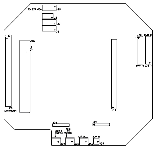
Figure 2: Panel Board, CPU Side
| Connector | Description | Type |
| J3 | VGA to CPU | 2x4 0.1" pitch female pin header |
| J6 | USB0 and USB1 to CPU | 2x5 0.1" pitch female pin header |
| J8 | USB2 and USB3 to CPU | 2x5 0.1" pitch female pin header |
| J14 | Data Acquisition to CPU | 50-pin 0.1" pitch female pin header |
| J15 | Multi I/O (4x RS-232, PS/2, utility) to CPU | 3M/Robinson Nugent P80 series, 80-pin high density |
| J23 | Variable voltage switch input | 1x2 pin 0.1" pitch male header |
| J25 | 5v switch input | 1x2 pin 0.1" pitch male header |
| J26 | Ethernet to CPU | 1x6 pin 0.1" pitch female pin header |
| J29 | VGA to VGA expansion board | 2x5 pin 0.1" pitch male header |
| J30 | COM5/COM6 to/from Emerald MM expansion board | 2x10 pin 0.1" pitch male header |
| J31 | Data Acquisition to expansion board | 2x25 pin 0.1" pitch male header |
| J33 | COM7/COM8 to/from Emerald MM expansion board | 2x10 pin 0.1" pitch male header |
| J34 | Power input to DC/DC power supply card in stack | 1x2 pin latching connector for cable interface up to xx AWG (Not installed) |
| J35 | Power input to DC/DC power supply card in stack | 1x2 pin latching connector for cable interface up to xx AWG |
| J36 | Power to CPU | 1x6 pin 0.1" pitch female header |
| Jumper | Definition |
| R2 | Determines whether power is provided directly to the DC/DC power supply board or through the on/off switch. Installed 0 Ohm resistor bypasses on/off switch. |
| R3 | Determines whether power is provided directly to the CPU board or through the on/off switch. Installed 0 Ohm resistor bypasses on/off switch. |