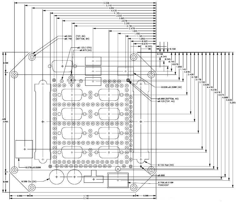
Figure 1: Top/Front End Cap Dimensions (DSC #PBEC-11-K)
Figure 1: Top/Front End Cap Dimensions (DSC #PBEC-11-K)

Figure 2: Bottom (Blank) End Cap Dimensions (DSC# PBEC-12-K)
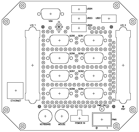
Figure 3: Top/Front End Cap Outline (DSC# PBEC-11-K)
The following table maps the silkscreen on the end cap to the connector designator on the top side of the panel board, and to the CPU connector on the bottom side of the panel board.
| Silkscreen Label | Top Connector Reference | Bottom Connector Reference | Bottom Connector Connects to |
| VGA | J2 | J3/J29 | CPU/VGA Expansion |
| USB1 | J5 | J8 | CPU |
| USB2 | J1 | J8 | CPU |
| USB3 | J4 | J6 | CPU |
| USB4 | J7 | J6 | CPU |
| SER1 | J13 | J15 | CPU |
| SER2 | J17 | J15 | CPU |
| SER3 | J19 | J15 | CPU |
| SER4 | J21 | J15 | CPU |
| SER5 | J12 | J30 | Serial expansion (EMM) |
| SER6 | J16 | J30 | Serial expansion (EMM) |
| SER7 | J18 | J33 | Serial expansion (EMM) |
| SER8 | J20 | J33 | Serial expansion (EMM) |
| I/O 1 | J9 | J14 | CPU |
| I/O 2 | J10 | J31 | Data acquisition expansion |
| Ethernet | J22 | J26 | CPU |
| Keyboard | J27 | J15 | CPU |
| Mouse | J28 | J15 | CPU |
| Power In | J24 | J35/J36 | CPU or DC/DC Supply Board |