System Integration
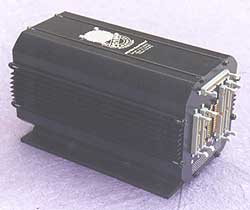
If you're looking for someone to put your system together, we can help. The photos here show a typical PC/104 embedded computer that we built for a defense customer. This particular system is used to control an unmanned helicopter and for flight simulation in the lab.
|
This assembly comprises the avionics for a military unmanned airborne vehicle. The right side contains an 8-board PC/104 stack consisting of 2 standard, 2 semicustom, and 4 full custom boards, along with 3 additional full custom boards mounted along the sides.
|
|
|
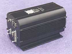
This side of the package contains the computer I/O connectors - Ethernet, 2 serial ports, video, and floppy - along with telemetry.
|
|
|
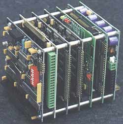
The 7-board PC/104 stack. The top board (on the left in the photo) is a custom telemetry board. The Jupiter-MM power supply is on the bottom of the stack at the right side in the photo.
|
|
Packaging and Cabling
The system is housed in a 10 inch CanTainer from Tri-M Systems with custom-designed end caps using the CT-EC00 blanks. Each CanTainer comes with one CT-EC00 blank end cap and one CT-EC01 end cap with prefabricated 4x DB9 and 2x DB25 cutouts. We discarded the CT-EC01 and designed our own cutout patterns.
A fan (part no. CT-FAN) is strategically positioned directly over the CPU and power supply for forced air cooling. Exhaust holes are provided at the I/O end of the case to enable airflow through the housing rather than simply within it.
Note that the CanTainer's internal mounting rails provide resistance to sliding the stack in direct proportion to the number of boards. In this case the resistance was significant, causing the rails to push out the opposite end slightly. The extruding portion can be easily cut off once the stack is in the desired position, before mounting the end caps.
If vibration is an issue, consider using a non-stackthrough configuration for the board at the bottom of the stack (or cut the pins on the PC/104 connectors) so that the PC/104 connector pins don't create a hazard for the cables.
All cabling was custom designed and contains latching connectors on the panel cutouts for mating with user cabling. Internally the cables are affixed with hot melt glue to protect against vibration. Each cable contains identification to mate it with the appropriate cutout in the end caps.
When using the CanTainer, select cable lengths so that there is enough working room to attach the cables to the end cap before attaching the end cap to the main housing. About 2-3 inches extra length is sufficient. Also the boards need to be set back from the ends of the housing so that the cables can fold back into the empty space when the end caps are attached.
For a 7-board stack measuring just under 5 inches in height with 13 cables, we used a 10 inch CanTainer with about 2.5 inches of room at each end. In a situation with fewer cables, the CanTainer could have been only 8 inches long.
PC/104 Boards
The 7 boards in the PC/104 stack, from bottom to top, are as follows:
- JMM-512-V512 DC/DC power supply from Diamond Systems to convert the 28VDC input to standard CPU voltages.
- 486 CPU at 100MHz with 4MB RAM from Ampro Computers, with Disk on Chip from M-Systems
- Thin coax Ethernet board from Ampro Computers
- 2 DMM-32 autocalibrating analog I/O boards from Diamond Systems
- IR104 relay and optoisolated digital input board from Tri-M Systems
- Custom telemetry board designed by the customer and built by Diamond Systems
Assembly
The assembly steps are as follows:
- Determine position of each board in the stack.
- Determine the connectors and cabling required and the desired locations on the housing. In this case all user I/O was mounted at one end, and all computer I/O was mounted at the other end.
- Design cutouts for connectors and fabricate the panels and main housing.
- Determine all configuration settings for each board in the stack and set the configurations.
- Assemble the stack using PC/104 spacers and standard hardware.
- Assemble the cables, making sure they are long enough to allow for mating to the end caps while the end caps are detached from the main housing.
- Install fan into CanTainer.
- Attach cables to the boards.
- Test system.
- Install the stack with cables attached into one end of the CanTainer and cut off any excess rail material.
- Install board stops inside the CanTainer to hold the boards in place. These parts are supplied with the CanTainer.
- Attach cables to end caps.
- Attach end caps to main housing.
- Take photos and create web page.
- Ship completed system to customer.
|