Figure 1: J3 - VGA to CPU
This section describes the connectors used to interface to the CPU card and expansion cards in the PC/104 stack.
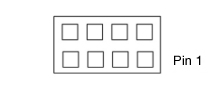
The J3 connector is a 2x4 pin, 0.1" pitch female header that interfaces directly to the VGA connector on the Diamond Systems Athena PC/104 CPU.
Figure 1: J3 - VGA to CPU
| GREEN | 1 | 2 | RED |
| BLUE | 3 | 4 | Ground |
| HSYNCH | 5 | 6 | DDC-Data |
| VSYNCH | 7 | 8 | DDC-Clock |

| RED | 1 | 2 | R-Ground |
| GREEN | 3 | 4 | G-Ground |
| BLUE | 5 | 6 | B-Ground |
| HSYNCH | 7 | 8 | DDC-Data |
| VSYNCH | 9 | 10 | DDC-Clock |
The J6 and J8 connectors are identical 2x5 pin, 0.1" pitch female headers that interface directly to the USB connectors on the Diamond Systems Athena PC/104 CPU.
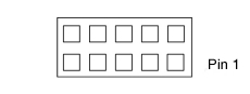
Figure 3: J6/J8 - USB to CPU
| Key (pin cut) | 1 | 2 | Shield |
| USB2 Pwr- | 3 | 4 | USB1 Pwr- |
| USB2 Data+ | 5 | 6 | USB1 Data+ |
| USB2 Data- | 7 | 8 | USB1 Data- |
| USB2 Pwr+ | 9 | 10 | USB1 Pwr+ |
The J26 connector is a 1x6 pin, 0.1" pitch female header that interfaces directly to the Ethernet connector on the Diamond Systems Athena, Prometheus and Elektra PC/104 CPUs.
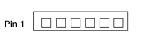
Figure 4: J26 - Ethernet to CPU
| 1 | Common |
| 2 | RX- |
| 3 | Common |
| 4 | RX+ |
| 5 | TX- |
| 6 | TX+ |
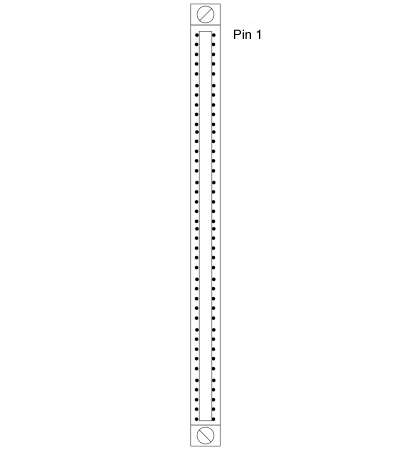
The J15 connector is an 80-pin high density connector, 3M part number P50-080-S-R1-TG, that provides the interfaces for the four serial ports from the CPU, the keyboard/mouse interface and certain utility signals. The power LED signal is routed to the power LED on the panel board. The speaker output signal is routed to the PC speaker on the panel board. The reset signal is routed to the reset connector on the panel board. All remaining signals on this connector, including the LPT port and other utility signals are not connected on the panel board and are not made available outside the enclosure.
| COM1 | DCD1 | 1 | 1 | STB- | LPT1 |
| DSR 1 | 2 | 2 | AFD- | ||
| RXD 1 | 3 | 3 | PD0 | ||
| RTS 1 | 4 | 4 | ERR- | ||
| TXD 1 | 5 | 5 | PD1 | ||
| CTS 1 | 6 | 6 | INIT- | ||
| DTR 1 | 7 | 7 | PD2 | ||
| RI 1 | 8 | 8 | SLIN- | ||
| Ground | 9 | 9 | PD3 | ||
| COM2 | DCD 2 | 10 | 10 | Ground | |
| DSR 2 | 11 | 11 | PD4 | ||
| RXD 2 | 12 | 12 | Ground | ||
| RTS 2 | 13 | 13 | PD5 | ||
| TXD 2 | 14 | 14 | Ground | ||
| CTS 2 | 15 | 15 | PD6 | ||
| DTR 2 | 16 | 16 | Ground | ||
| RI 2 | 17 | 17 | PD7 | ||
| Ground | 18 | 18 | Ground | ||
| COM3 | DCD 3 | 19 | 19 | ACK- | |
| DSR 3 | 20 | 20 | Ground | ||
| RXD 3 | 21 | 21 | BUSY | ||
| RTS 3 | 22 | 22 | Ground | ||
| TXD 3 | 23 | 23 | PE | ||
| CTS 3 | 24 | 24 | Ground | ||
| DTR 3 | 25 | 25 | SLCT | ||
| RI 3 | 26 | 26 | KB Clk | Keyboard | |
| Ground | 27 | 27 | KB/MS V- | ||
| COM4 | DCD 4 | 28 | 28 | KB Data | |
| DSR 4 | 29 | 29 | KB/MS V+ | ||
| RXD 4 | 30 | 30 | MS Clk | Mouse | |
| RTS 4 | 31 | 31 | KB/MS V- | ||
| TXD 4 | 32 | 32 | MS Data | ||
| CTS 4 | 33 | 33 | KB/MS V+ | ||
| DTR 4 | 34 | 34 | Ground | Utilities B | |
| RI 4 | 35 | 35 | Reset- | ||
| Ground | 36 | 36 | ATX Power | ||
| Utilities A | +5V Out | 37 | 37 | KB Lock | |
| Speaker Out | 38 | 38 | IR RX | ||
| IDE Drive LED | 39 | 39 | IR TX | ||
| Power LED | 40 | 40 | +3VSB |
The J9 connector is a 2x25 pin, 0.1" pitch female header that routs signals directly from the data acquisition connector on the Athena, Prometheus or Elektra PC/104 CPUs. These signals include 16, 16-bit analog inputs, four 12-bit analog outputs and 24 digital I/O lines, along with control for two counter/timers.
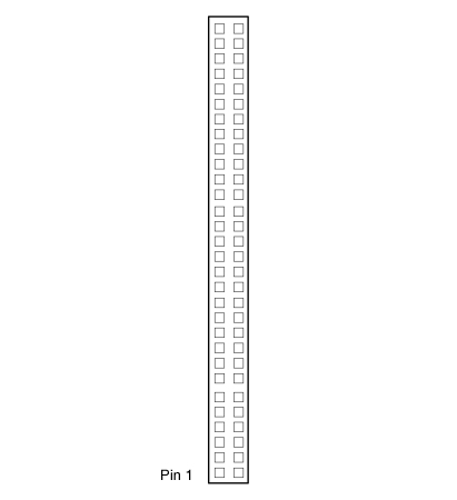
Figure 6: J14 - Data Acquisition to CPU
| DIO A0 | 1 | 2 | DIO A1 |
| DIO A2 | 3 | 4 | DIO A3 |
| DIO A4 | 5 | 6 | DIO A5 |
| DIO A6 | 7 | 8 | DIO A7 |
| DIO B0 | 9 | 10 | DIO B1 |
| DIO B2 | 11 | 12 | DIO B3 |
| DIO B4 | 13 | 14 | DIO B5 |
| DIO B6 | 15 | 16 | DIO B7 |
| DIO C0 | 17 | 18 | DIO C1 |
| DIO C2 | 19 | 20 | DIO C3 |
| DIO C4 / Gate 0 | 21 | 22 | DIO C5/Gate 1 |
| DIO C6 / Clk 1 | 23 | 24 | DIO C7/Out 0 |
| Ext Trig | 25 | 26 | Tout 1 |
| +5V Out | 27 | 28 | Dground |
| Vout 0 | 29 | 30 | Vout 1 |
| Vout 2 | 31 | 32 | Vout 3 |
| Aground (Vout) | 33 | 34 | Aground (Vin) |
| Vin 0 | 35 | 36 | Vin 8 |
| Vin 1 | 37 | 38 | Vin 9 |
| Vin 2 | 39 | 40 | Vin 10 |
| Vin 3 | 41 | 42 | Vin 11 |
| Vin 4 | 43 | 44 | Vin 12 |
| Vin 5 | 45 | 46 | Vin 13 |
| Vin 6 | 47 | 48 | Vin 14 |
| Vin 7 | 49 | 50 | Vin 15 |
The J36 connector is a 1x6 pin 0.1" pitch header that provides +5v power to the CPU card. For this power interface to be active, either the power switch bypass jumper 0 Ohm resistor at R3 must be installed or the power switch must be cabled to connector J25.
Figure 7: J36 - Power to CPU
| 1 | +5V In |
| 2 | Ground |
| 3 | Ground |
| 4 | N/C |
| 5 | Ground |
| 6 | +5V In |
The data acquisition connector at J31 is designed to provide an interface to the outside from a 50-pin connector on an expansion board in the PC/104 stack. This connector is a 2x25 pin, 0.1" pitch male header that connects pin for pin with connector J10 on the user side of the panel board.
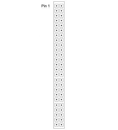
Figure 8: J31 - Data Acquisition to Expansion Board
| I/O Pin 1 | 1 | 2 | I/O Pin 26 |
| I/O Pin 2 | 3 | 4 | I/O Pin 27 |
| I/O Pin 3 | 5 | 6 | I/O Pin 28 |
| I/O Pin 4 | 7 | 8 | I/O Pin 29 |
| I/O Pin 5 | 9 | 10 | I/O Pin 30 |
| I/O Pin 6 | 11 | 12 | I/O Pin 31 |
| I/O Pin 7 | 13 | 14 | I/O Pin 32 |
| I/O Pin 8 | 15 | 16 | I/O Pin 33 |
| I/O Pin 9 | 17 | 18 | I/O Pin 34 |
| I/O Pin 10 | 19 | 20 | I/O Pin 35 |
| I/O Pin 11 | 21 | 22 | I/O Pin 36 |
| I/O Pin 12 | 23 | 24 | I/O Pin 37 |
| I/O Pin 13 | 25 | 26 | I/O Pin 38 |
| I/O Pin 14 | 27 | 28 | I/O Pin 39 |
| I/O Pin 15 | 29 | 30 | I/O Pin 40 |
| I/O Pin 16 | 31 | 32 | I/O Pin 41 |
| I/O Pin 17 | 33 | 34 | I/O Pin 42 |
| I/O Pin 18 | 35 | 36 | I/O Pin 43 |
| I/O Pin 19 | 37 | 38 | I/O Pin 44 |
| I/O Pin 20 | 39 | 40 | I/O Pin 45 |
| I/O Pin 21 | 41 | 42 | I/O Pin 46 |
| I/O Pin 22 | 43 | 44 | I/O Pin 47 |
| I/O Pin 23 | 45 | 46 | I/O Pin 48 |
| I/O Pin 24 | 47 | 48 | I/O Pin 49 |
| I/O Pin 25 | 49 | 50 | I/O Pin 50 |
Connectors J30 and J33 provide an interface to a serial port expansion board such as a Diamond Systems Emerald MM-4. Each connector is a 2x10 pin, 0.1" pitch male header designed to cable interface to the connectors on the Emerald MM-4. The tables below shows the pin definition for the RS232, RS422 and RS485 protocols supported by the Emerald MM-4.
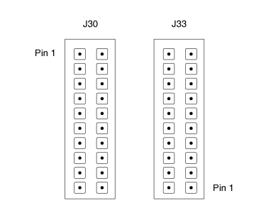
Figure 9: J30 /J33 - Serial to Expansion Board
| J30 | J33 | |||||||
| DCD 1 | 1 | 2 | DSR 1 | DCD 3 | 1 | 2 | DSR 3 | |
| RXD 1 | 3 | 4 | RTS 1 | RXD 3 | 3 | 4 | RTS 3 | |
| TXD 1 | 5 | 6 | CTS 1 | TXD 3 | 5 | 6 | CTS 3 | |
| DTR 1 | 7 | 8 | RI 1 | DTR 3 | 7 | 8 | RI 3 | |
| GND | 9 | 10 | NC | GND | 9 | 10 | NC | |
| DCD 2 | 11 | 12 | DSR 2 | DCD 4 | 11 | 12 | DSR 4 | |
| RXD 2 | 13 | 14 | RTS 2 | RXD 4 | 13 | 14 | RTS 4 | |
| TXD 2 | 15 | 16 | CTS 2 | TXD 4 | 15 | 16 | CTS 4 | |
| DTR 2 | 17 | 18 | RI 2 | DTR 4 | 17 | 18 | RI 4 | |
| GND | 19 | 20 | NC | GND | 19 | 20 | NC | |
| J30 | J33 | |||||||
| NC | 1 | 2 | NC | NC | 1 | 2 | NC | |
| TXD+ 1 | 3 | 4 | TXD- 1 | TXD+ 3 | 3 | 4 | TXD- 3 | |
| GND | 5 | 6 | RXD- 1 | GND | 5 | 6 | RXD- 3 | |
| RXD+ 1 | 7 | 8 | NC | RXD+ 3 | 7 | 8 | NC | |
| GND | 9 | 10 | NC | GND | 9 | 10 | NC | |
| NC | 11 | 12 | NC | NC | 11 | 12 | NC | |
| TXD+ 2 | 13 | 14 | TXD- 2 | TXD+ 4 | 13 | 14 | TXD- 4 | |
| GND | 15 | 16 | RXD- 2 | GND | 15 | 16 | RXD- 4 | |
| RXD+ 2 | 17 | 18 | NC | RXD+ 4 | 17 | 18 | NC | |
| GND | 19 | 20 | NC | GND | 19 | 20 | NC | |
| J30 | J33 | |||||||
| NC | 1 | 2 | NC | NC | 1 | 2 | NC | |
| TXD/RXD+ 1 | 3 | 4 | TXD/RXD- 1 | TXD/RXD+ 3 | 3 | 4 | TXD/RXD- 3 | |
| GND | 5 | 6 | NC | GND | 5 | 6 | NC | |
| NC | 7 | 8 | NC | NC | 7 | 8 | NC | |
| GND | 9 | 10 | NC | GND | 9 | 10 | NC | |
| NC | 11 | 12 | NC | NC | 11 | 12 | NC | |
| TXD/RXD+ 2 | 13 | 14 | TXD/RXD- 2 | TXD/RXD+ 4 | 13 | 14 | TXD/RXD- 4 | |
| GND | 15 | 16 | NC | GND | 15 | 16 | NC | |
| NC | 17 | 18 | NC | NC | 17 | 18 | NC | |
| GND | 19 | 20 | NC | GND | 19 | 20 | NC | |
Connector J35 is used to interconnect the front panel power input to a DC/DC power supply board, such as the Diamond Systems Jupiter MM, in the PC/104 stack. When this interface is used, the direct CPU power interface through connector J36 is not used. Instead, the CPU is powered through the PC/104 bus by the power supply board. This connector is cabled to the DC/DC power supply board as indicated in the cabling drawing, below. To activate this interface without the use of the power switch, the bypass jumper at R2 must be installed with a 0 Ohm resistor. To activate this interface with the use of the power switch, the power switch must be cabled to connector J23.

Figure 10: J35 - Power to DC/DC Power Supply Board
| 1 | Positive Input |
| 2 | Input Return |