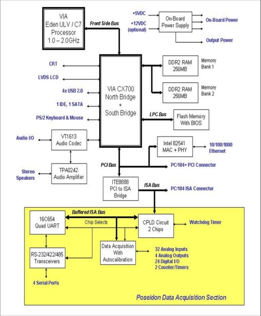
Poseidon is an embedded CPU board in an EPIC form factor that integrates CPU and data acquisition circuitry into a single board.
Poseidon conforms to the EPIC standard with expansion support via PC/104-Plus, an embedded standard that is based on the ISA and PCI buses and provides a compact, rugged mechanical design for embedded systems. PC/104 modules feature a pin and socket connection system in place of card edge connectors, as well as mounting holes for stand-offs in each corner. The result is an extremely rugged computer system fit for mobile and miniature applications. PC/104 modules stack together with 0.6” spacing between boards (0.662” pitch including the thickness of the PCB).
Poseidon uses the PCI bus internally to connect the Ethernet circuit to the processor. It uses the ISA bus internally to connect serial ports 3 and 4, as well as the data acquisition circuit, to the processor. Both the ISA and PCI buses are brought out to expansion connectors for the connection of add-on boards. Diamond Systems manufactures a wide variety of compatible PC/104 add-on boards for analog I/O, digital I/O, counter/timer functions, serial ports, and power supplies.
The Poseidon board is an all-in-one embedded CPU with the following key system and data acquisition features.
- 2 ports 16550-compatible
- 2 ports 16850-compatible with 128-byte FIFOs and RS-232, RS-422 and RS-485 capability, with RS-422/485 termination.
Figure 1 shows the Poseidon functional blocks.
This section describes the major Poseidon subsystems.
Two processor options are available for the Poseidon board.
The North and South bridge are integrated in the on-board VIA CX700 chip.
The board accommodates 512MB of SDRAM system memory soldered on the board. No expansion connector is provided for additional memory.
The board also includes flash memory for storage of BIOS and user programs. Flash memory is accessible via the on-board ISA bus.
Video circuitry is provided by the VIA CX700 chipset and includes,
The design provides AC97 audio support derived from the South Bridge chip. The Via VT1612A CODEC provides audio processing. Give special attention to design and routing to minimize noise on the audio I/O lines.
Audio I/O includes,
The board includes audio power amplifier circuitry for stereo speaker output. The amplifier circuit is powered by +5VDC from the board. User DC control of volume is also provided, which overrides the software settings.
The board supports 10-/100-/1000BaseT (Gigabit) Ethernet. Magnetics are included on the board so that a complete circuit is provided.
The board provides the following data acquisition capabilities.
| Type of I/O | Characteristics |
| Analog Input | 32 single-ended/16 differential inputs,16-bit resolution |
| Analog Output | Four analog outputs, 12-bit resolution |
| Digital I/O | 24 programmable digital I/O, 3.3V and 5V logic compatible |
| Counter/Timers | One 24-bit counter/timer for A/D sampling rate control One 16-bit counter/timer for user counting and timing functions |
The board provides the following standard system peripherals.
| Peripheral | Characteristics |
| Serial ports | Four serial ports |
| PS/2 ports | Keyboard and mouse |
| USB ports | Four USB 2.0 function ports |
| IDE ports | One 44-pin connector for HDD or FlashDisk Compact flash socket One standard S-ATA connector for up to two S-ATA HDD |
Serial ports 3 and 4 can be BIOS-selected for RS-232, RS-485 or RS-422. Termination resistors of 120 ohms can be jumper-enabled on these two ports.
Console redirection feature is incorporated. This feature enables keyboard input and character video output to be routed to one of the serial ports.
The board contains provision for mounting a solid state IDE flashdisk module with capacities ranging from 32MB and greater. The module mounts onto the board using a 44-pin 2mm pitch header and a hold-down mounting hole with spacer and screws.
The PCI bus is the primary connection between the North/South bridge, Ethernet, and PC/104-Plus devices.
The ISA bus is exposed on PC/104 connectors for use by add-on modules. The PC/104-Plus connectors allow expansion above the board only.
The power supply is an on-board converter, allowing an input range of +5VDC, ±5%. Jumper selection allows power to be taken from the PC-104 bus and not from the on-board converter.
The power supply includes ATX power switching and ACPI power management support. The master +5V input is controlled by the ATX function with an external switch input.
The board includes a backup battery for CMOS RAM and real-time clock backup. The battery life is greater than four years. A connector and jumper are provided to disable the on-board battery and enable the use of an external battery, instead.
A watchdog timer (WDT) circuit consists of a programmable timer.
Figure 2 shows the Poseidon board layout, including connectors, jumper blocks and mounting holes.
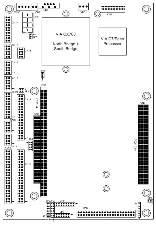
The following table lists the connectors on the Poseidon board.
| Connector | Description | Manufacturer Part No. |
| CN1 | LCD panel (LVDS interface) | JST Part No.: BM30B-SRDS-G-TF |
| CN2 | Primary IDE | Standard 2x22, 0.1” header |
| CN3 | PC/104-Plus PCI bus connector | - |
| CN4 | LCD backlight | Digikey A19470 |
| CN5 | Serial ATA | - |
| CN6 | PC/104, ISA bus A,B | EPT 962-60323-12 |
| CN7 | PC/104, ISA bus C,D | EPT 962-60203-12 |
| CN8 | External battery | Digikey A1921 |
| CN9 | Input Power | Molex |
| CN10 | External auxiliary power (output) | Digikey 640456-4 |
| CN11 | Speaker | Standard 2x4, 2mm header |
| CN12 | Data acquisition digital I/O, 34-pin | Standard 2x17, 2mm header |
| CN13 | Data acquisition analog I/O, 40-pin | Standard 2x20, 2mm header |
| CN14 | I/O panel power | Standard 2x10, 2mm header |
| CN15 | Audio I/O | Standard 2x5, 2mm header |
| CN16 | VGA | Standard 2x5, 2mm header |
| CNJ17 | Ethernet | Standard 2x5, 2mm header |
| CN18 | Standard button/LED utility connector | Standard 2x4, 2mm header |
| CN19 | PS/2 Mouse and keyboard | Standard 2x4, 2mm header |
| CN20 | RS-232/RS-485/RS-422 serial I/O (COM1-4) | Standard 2x20, 2mm header |
| CN21 | USB 0/1, USB 2/3 (USB 2.0) | Standard 2x10, 2mm header |
| J1 | Standard JTAG interface (Factory use) | - |
| J2 | Voltage reference test point (Factory use) | - |
The following table lists the jumpers on the Poseidon board.
| Jumper | Description |
| JP1 | PCI voltage selection |
| JP2 | DAQ configuration |
| JP3 | COM3/4 and DAQ IRQ selection |
| JP4 | DAQ single-ended/differential selection |
| JP5 | DAC range configuration |
| JP6 | Battery power selection |
| JP7 | ATX power |
| JP8 | RS-422/485 termination |
| JP9 | DIO pull-up/pull-down configuration |