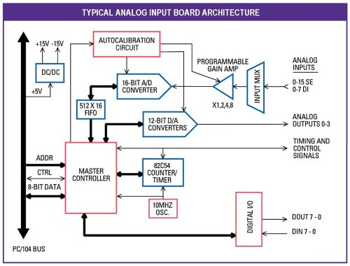
A typical A/D (analog to digital converter) board contains the following major subsections:
- Input multiplexors - enable multiple input channels to share a single A/D circuit
- Gain circuit - enables you to select different amplification levels based on the input signal range
- A/D converter - converts the analog input to a digital value
- FIFO - stores A/D data on board until the processor is ready to read it out
- Counter/timer - for counting applications and for A/D sample rate control
- Control logic - controls all the timing of the various circuits on the board
- Bus interface - transfers commands and data between the board and the CPU
- D/A converter (optional) - provides analog output functions
- Digital I/O (optional) - provides digital input and output functions
- Power supply - provides clean power for the analog circuitry, typically +/-15V


 prev
prev