|
| DIAMOND-MM-16R-AT PC/104 16-Bit Analog I/O Module with Autocalibration |
 |
|
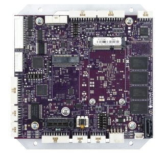
| Saturn Rugged Apollo Lake x7-E3950 SBC with Data Acquisition and PCIe/104 Expansion |
 |
|
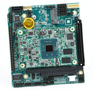
| Athena IV COM-Express PC/104 SBC with Data Acquisition |
 |
| | |
|
| |
Products
> I/O Expansion Modules
> Analog I/O Modules
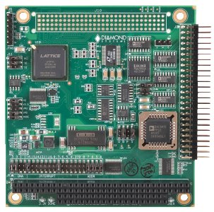
> Diamond-MM-32DX-AT |   | DIAMOND-MM-32DX-AT Analog I/O PC/104 Module with Advanced Automatic Autocalibration |  |
| | |
| DMM-32DX-AT is Diamond Systems' most advanced embedded A/D board. It includes a comprehensive suite of analog and digital features to fit a wide variety of embedded application needs:
The 32 A/D input channels feature high-accuracy 16-bit resolution, 250KHz maximum sampling rate, programmable input ranges, and user-selectable single-ended / differential configuration. The 4 D/A output channels feature user-selectable output ranges as well as a programmable waveform generator feature, 16-bit standard, 12-bit optional. The 24 digital I/O feature bit by bit direction programmability as well as buffers for enhanced output current of -15mA (logic 1) / 64mA (logic 0). The on-board programmable counter/timer circuitry includes a 32-bit counter/timer for A/D and D/A sample timing, as well as a 16-bit counter/timer for general counting, timing, and programmable interrupt functions. Extended temperature operation of -40°C to +85°C is tested and guaranteed. Using our patented auto-autocalibration technology, DMM-32DX-AT will provide accurate analog measurements across its entire rated operating temperature range, ensuring reliable performance for critical applications. Our advanced Universal Driver software is included free with DMM-32DX-AT and all our SBC and I/O boards. The Universal Driver provides a programming library that simplifies control of all the board's features and enables you to develop your application software quickly. Board uses only ceramic capacitators for durability in high altitudes and other harsh environments.
 |
Industry-Leading Auto-Autocalibration Provides Maximum Accuracy |
DMM-32DX-AT includes Diamond Systems patented auto-autocalibration technology. This circuitry enables automatic calibration of the board in response to changes in temperature without requiring any involvement by the user or application program. An on-board microcontroller monitors the board's temperature and uses on-board calibration circuitry to bring the board into calibration whenever needed, totally automatically. Typical accuracy post-calibration is +/-1LSB. The calibration threshold is set for 5 degrees C, which typically limits measurement errors to only +/-2 to +/-3LSB pre-calibration. Click here to learn more about this advanced technology patented by Diamond Systems.
|
Quality Design Ensures Reliable Measurements |
Quality and precision are evident throughout the design of DMM-32DX-AT: Low-drift circuitry: The reference voltage is the foundation of any A/D board's accuracy. On DMM-32DX-AT, a precision low-drift analog voltage reference chip is used as the basis for the A/D circuit. This low-drift device limits natural measurement errors induced by changes in the ambient temperature of the system. Low noise design: A 16-bit A/D converter measures signals down to the level of tens of microvolts. This extreme sensitivity can be easily swamped by noise from nearby high-speed, high-power digital circuitry such as the CPU. On DMM-32DX-AT, careful attention is paid to component placement and trace layout in order to minimize noise in the analog circuitry. Digital and analog circuits are kept separate on the board and are placed over their respective power and ground plane, which are also separated. Digital signals that cross over into the analog region pass through isolating resistors at the transition point to further minimize digital noise effects. In addition, components with high power supply rejection ratio specifications are used in the design to further enhance immunity to power supply noise. This results in low-noise, reliable analog readings for all input voltage ranges. The analog power supply is isolated from analog and digital power and ground planes. High bandwidth: The maximum sampling rate of an A/D board is often only achievable when sampling a single channel. Limited bandwidth in the analog input
circuit can produce significant errors when conducting high speed sampling across multiple channels, because the input circuit cannot settle on the new input voltage in time to present an accurate signal to the A/D converter. On DMM-32DX-AT, this issue has been specifically addressed and tested. The analog circuit bandwidth supports accurate full-speed sampling for a single channel or any number of channels, in all configurations and all input ranges.
|
Advanced Architecture |
At the core of DMM-32DX-AT is an FPGA with advanced logic that provides important features needed to get the most out of your system:
The on-board programmable A/D sample clock lets you select the precise sample rate you need for your application. Multiple A/D clocking methods are supported, including the on-board clock, external clock or software command. The 1024-sample A/D FIFO ensures reliable performance at any speed in any operating system. It contains a novel programmable threshold that lets you fine-tune the A/D operation to your application needs. For low sample rates, a lower threshold lets you get data sooner, while for high sample rates, a larger threshold prevents excessive consumption of valuable processor bandwidth. Advanced sampling and data transfer techniques provide flexibility in meeting your application's unique requirements. A D/A waveform generator is provided with programmable waveforms and output rates. It can be used with 1, 2, or 4 channels simultaneously. The on-board EEPROM contains free space that is easily accessible by the user's application program using our Universal Driver software. This non-volatile storage may be used for any desired function, such as storing key system variables in case of power loss.
|
Ruggedization for Real World Applications |
DMM-32DX-AT is tested and guaranteed for -40 to +85°C operating temperature off the shelf. Additional services can enhance the board's ruggedness and reliability: All configuration jumpers can be replaced with hardwired 0-ohm configuration resistors using dedicated footprints on the board for use in high-vibration environments. Optional conformal coating and latching connectors provide additional protection if needed. Contact Diamond Systems for information on these options. No tantalum or electrolytic capacitors are used in construction of board.
|
Universal Driver Software |
Universal Driver software provides a high-level programming library for DMM-32DX-AT and all of Diamond Systems I/O boards, as well as the data acquisition circuitry on our SBC boards. All the features described above are supported with easy-to-use function calls, resulting in a reduced learning curve and shortened application development time. The Universal Driver works with Linux, Windows 2000/XP, Windows CE and DOS. Application examples and projects are included for each function, each board, and each operating system to provide a quick starting point for learning and development. Click here to learn more.
| Cable |
Description |
Drawing |
| C-34-18 |
34-conductor 18" ribbon cable |
Show |
| C-50-18 |
50-conductor .1" pitch 18" ribbon cable, Data acquisition Cable |
Show |
|
A/D Sampling Methods |
DMM-32DX-AT provides a 3-stage A/D timing system that provides the highest degree of flexibility:
A/D Trigger: The A/D may be triggered in one of three ways: a software command, the on-board programmable clock, or an external trigger. The external trigger is often used to synchronize the A/D with an external event, such as a rotor reaching a particular angular position or a moving object reaching a specified position. Sampling: Once the trigger is received, the A/D can sample the input signals in several ways. The simplest way is to remain fixed on a single channel for high speed data acquisition. The next option is called multi-channel round robin sampling. The A/D sequences through a selected range of channels one at a time. Each trigger causes the next channel to be sampled; when the last channel has been sampled, the next trigger will start over at the first channel. The third way is multi-channel scan sampling, in which an entire group of channels is sampled in rapid succession on each trigger. This method allows for parallel sampling of multiple channels on essentially identical time bases, so that multiple waveforms or signals can be acquired simultaneously and viewed together. Data transfer to memory: Once the data is acquired on board, it must eventually be transferred to the computer's memory for use by the application program. This transfer operation can also be done in several ways. For low-speed applications, the application program can simply read the A/D data after each A/D conversion. For medium speed applications, the data is stored in an on-board 1024-sample FIFO, and the application can read out a block of data at one time for convenience. For high speed applications, the FIFO is programmed to generate an interrupt when a desired threshold is reached, and an interrupt routine embedded in the software driver reads out the FIFO contents all at once automatically. The FIFO threshold is programmable, so this method can be used for low-speed sampling as well. For low sample rates, a lower threshold lets you get data sooner. For high sample rates, a larger threshold prevents excessive consumption of valuable processor bandwidth and ensures reliable, gap-free performance at full speed in any operating system.
|
D/A Features |
DMM-32DX-AT includes 4 12-bit D/A channels. These can be programmed one at a time, or they can be updated simultaneously. Four different output voltage ranges are available with jumper settings.
A waveform generator feature is included on the board. It includes a 1,024-sample data buffer that can be used to store 1, 2, or 4 waveforms, all of which can be output simultaneously. The data is output in frames, where a frame contains one data point for each channel being used. The output rate is programmable using the on-board counter/timer circuit up to a rate of 100,000 frames per second.
|
Digital and Counter/Timer I/O Features |
DMM-32DX-AT features 24 digital I/O lines and 2 82C54-type counter/timers just like its predecessor DMM-32-AT. The I/O lines can be programmed for input or output in groups of 8 bits. In output mode the lines are buffered for enhanced output current capability. All DIO lines feature jumper-selectable pull-up / pull-down resistors as well as ESD protection devices to help prevent field failures.
The counter/timers emulate an 8254. Counter 0 is standalone and can be used for general purpose counting, timing, or timer-based interrupts. Counters 1 and 2 are joined together to provide a 32-bit timer for A/D sample rate control or D/A waveform output control.
|
I/O Connector Pinouts |
|
Analog I/O Header
| Analog Ground |
1 |
2 |
Analog Ground |
| Vin 0 / 0+ |
3 |
4 |
Vin 16 / 0- |
| Vin 1 / 1+ |
5 |
6 |
Vin 17 / 1- |
| Vin 2 / 2+ |
7 |
8 |
Vin 18 / 2- |
| Vin 3 / 3+ |
9 |
10 |
Vin 19 / 3- |
| Vin 4 / 4+ |
11 |
12 |
Vin 20 / 4- |
| Vin 5 / 5+ |
13 |
14 |
Vin 21 / 5- |
| Vin 6 / 6+ |
15 |
16 |
Vin 22 / 6- |
| Vin 7 / 7+ |
17 |
18 |
Vin 23 / 7- |
| Vin 8 / 8+ |
19 |
20 |
Vin 24 / 8- |
| Vin 9 / 9+ |
21 |
22 |
Vin 25 / 9- |
| Vin 10 / 10+ |
23 |
24 |
Vin 26 / 10- |
| Vin 11 / 11+ |
25 |
26 |
Vin 27 / 11- |
| Vin 12 / 12+ |
27 |
28 |
Vin 28 / 12- |
| Vin 13 / 13+ |
29 |
30 |
Vin 29 / 13- |
| Vin 14 / 14+ |
31 |
32 |
Vin 30 / 14- |
| Vin 15 / 15+ |
33 |
34 |
Vin 31 / 15- |
| Vout 3 |
35 |
36 |
Vout 2 |
| Vout 1 |
37 |
38 |
Vout 0 |
| Vref Out |
39 |
40 |
Analog Ground |
| Clk Out / Dout 3 |
41 |
42 |
Counter 2 Out / Dout 2 |
| S/H Out / Dout 1 |
43 |
44 |
Counter 0 Out / Dout 0 |
| Ext. Clk In / Din 3 |
45 |
46 |
External Gate / Din 2 |
| Gate 0 / Din 1 |
47 |
48 |
Counter 0 In / Din 0 |
| +5V |
49 |
50 |
Digital Ground |
|
|
Digital I/O Header
| A7 |
1 |
2 |
A6 |
| A5 |
3 |
4 |
A4 |
| A3 |
5 |
6 |
A2 |
| A1 |
7 |
8 |
A0 |
| B7 |
9 |
10 |
B6 |
| B5 |
11 |
12 |
B4 |
| B3 |
13 |
14 |
B2 |
| B1 |
15 |
16 |
B0 |
| C7 |
17 |
18 |
C6 |
| C5 |
19 |
20 |
C4 |
| C3 |
21 |
22 |
C2 |
| C1 |
23 |
24 |
C0 |
| Latch |
25 |
26 |
Ack |
| NC |
27 |
28 |
NC |
| RS232 TX |
29 |
30 |
RS232 RX |
| RS485+ |
31 |
32 |
RS485- |
| +5V |
33 |
34 |
Digital Ground |
|
| Analog Inputs |
| Number of inputs |
32 single-ended, 16 differential, or 16 SE + 8 DI; user selectable |
| A/D resolution |
16 bits (1/65,536 of full scale) |
| Bipolar ranges |
10V, 5V, 2.5V, 1.25V, 0.625V |
| Unipolar ranges |
0-10V, 0-5V, 0-2.5V, 0-1.25V, 0-.625V, |
| Input bias current |
100pA max |
| Overvoltage protection |
35V on any analog input without damage |
| Input Impedance |
10^13 ohms |
| Nonlinearity |
3LSB, no missing codes |
| Conversion rate |
250,000 samples/sec.max |
| On-board FIFO |
1024 16-bit samples |
| Calibration |
Automatic;values stored in EEPROM |
| Analog Outputs |
| Number of outputs |
4 |
| D/A resolution |
16-bits (1/65536 of full scale) standard, 12-bits (1/4096 of full scale) optional |
| Output ranges |
5, 10, 0-5, 0-10, 2, 5V, programmable in I/O, 53mV steps |
| Output current |
5mA max per channel |
| Settling time |
6'S max to 0.01% |
| Relative accuracy |
1 LSB |
| Nonlinearity |
1 LSB, monotonic |
| Reset |
Reset to zero-scale or mid-scale (jumper selectable) |
| Calibration |
Automatic; values stored in EEPROM |
| Waveform Buffer |
1,024 samples, cyclical |
| Digital I/O |
| Main I/O |
24 programmable I/O |
| Input current |
1A max |
| Output current |
|
| Logic 0 |
64mA max per line |
| Logic 1 |
-15mA max per line |
| Auxilary I/O |
4 inputs, 4 outputs, optional use as trigger/control lines |
| Counter/Timers |
| A/D Pacer clock |
32-bit down counter (2 82C54 counters cascaded) |
| Clock source |
10MHz on-board clock or external signal |
| General purpose |
16-bit down counter (1 82C54 counter) |
| General |
| Power supply |
+5VD 10%@410mA typ |
| Operating temperature |
-40°C to +85°C |
| Weight |
3.4oz/96g |
| MTBF |
972,275 hours at +20°C |
| RoHS |
Compliant |
| | |
|


; "Diamond-MM-32DX-AT: I/O Expansion Modules, An industry-leading family of PC/104, PC/104-<i>Plus</i>, PCIe/104 / OneBank, PCIe MiniCard, and FeaturePak data acquisition modules featuring A/D, D/A, DIO, and counter/timer functions., PC/104")